Course project, Microsystem Technology
Piezoelectric Smart Flooring for Robot Localisation
Floor tiles that sense where warehouse robots are, and harvest energy from them as they pass.
- State Estimation
- Hardware
My contributions
- Proposed localising warehouse robots from the floor itself: piezoelectric tiles sense passing robots, and RFID checkpoints identify them.
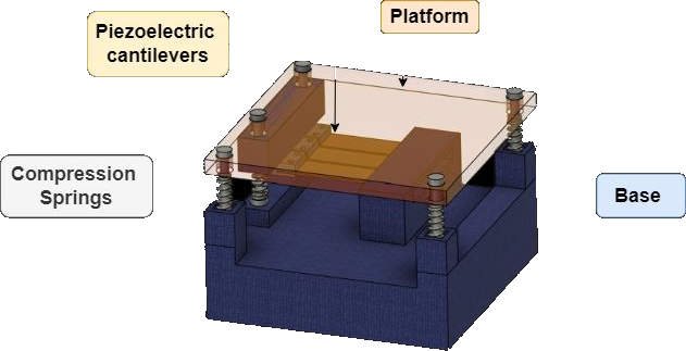
- Designed a floor tile in Fusion 360 with three parallel PZT-5A bimorph cantilevers, a proof mass, spring supports and corner sensors.
- Simulated the cantilever in ANSYS (coupled-field harmonic analysis) under the loads of five industrial mobile robots.
An open project for the Microsystem Technology course at NITK, taught by Prof. S. M. Kulkarni. The idea: instead of giving every warehouse robot LiDAR or cameras to localise itself, let the floor do it. Piezoelectric tiles at key points sense robots driving over them and, at the same time, turn that motion into electrical energy. It is a direction we felt had real potential for further research.
The tile
Each tile holds three PZT-5A bimorph cantilevers in parallel, fixed at one end with a 50 g proof mass at the other, under a transparent platform on four compression springs, with a circular piezo sensor at each spring. A robot rolling over pushes the platform down and bends the beams, which generate a voltage; after it passes, the beams keep ringing and the springs reset the platform, so energy is captured from both the press and the release. A rectifier circuit conditions the output.
Localising robots from the floor
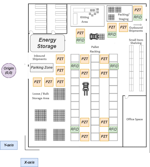
Tiles go where traffic concentrates: intersections, parking and charging zones, pallet-picking areas and workstations. A robot's pressure and vibration signature tells the system that a robot is on a tile and roughly where; RFID readers at checkpoints say which robot it is. A graph-based probabilistic model of the warehouse fuses the two with known routes and timing, tracking each robot between RFID reads. The same signals give a live robot-density map for fleet management.
Simulation
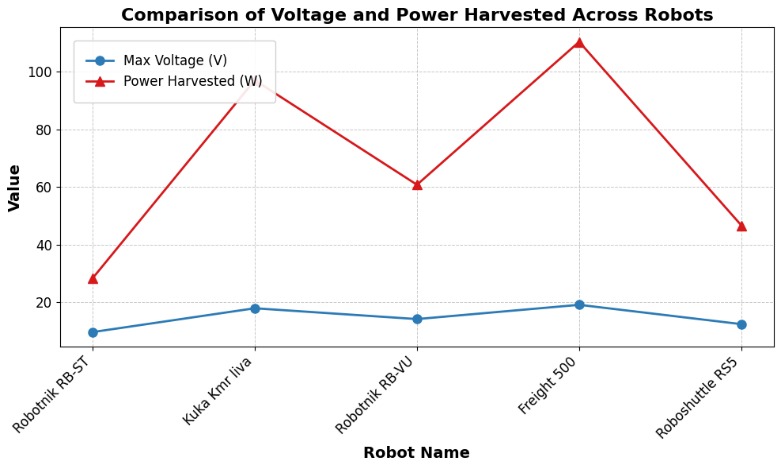
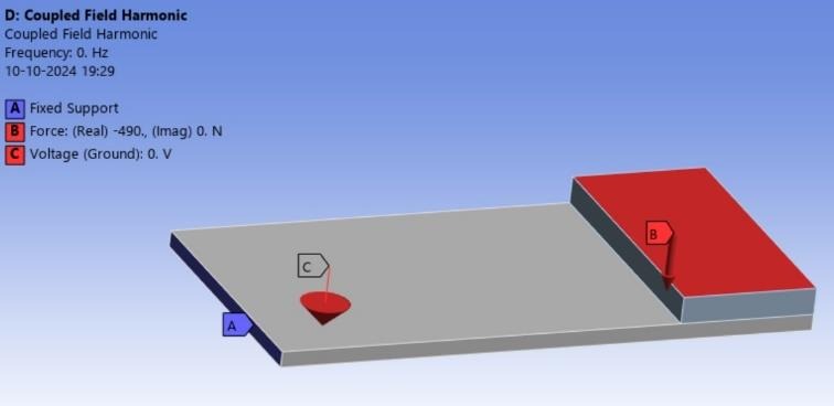
The cantilever (100 x 50 x 3 mm) was simulated in ANSYS with a coupled-field harmonic analysis, under the loads of five industrial mobile robots, from the Robotnik RB-STEEL to the Freight 500 carrying its full payload. The beam deflected up to about 0.019 mm, and the simulated output peaked at about 19 V under the Freight 500.
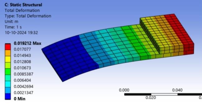
This was a simulation study. A physical prototype and real robot trials were the natural next step.
Gallery